NT$ 11,600
Home » Modular Synthesizer » Sequencer » WMD [已絕版] Sequential Switch Matrix
![WMD [已絕版] Sequential Switch Matrix - Main Image](https://dywzyq1lym3hh.cloudfront.net/uploads/product/cover/1381/SSM.png)


Our take on an essential module
Four inputs can be routed with individual buttons to four outputs. Those routing settings are stored in an array of matrices that can be sequenced or controlled with CV. Preset routing, feedback loops, chop sequences, trigger blasts (with expander), four-bit-wavetable-synthesis, and dramatic controllable mayhem are all possible.
- Four inputs can be routed individually to four outputs
- Saveable routing matrices for a variety of effects
- Controllable via sequencer or CV
Concept
The Sequential Switch Matrix (SSM) is a four input, four output signal routing system. The digitally controlled analog signal paths allow for a variety of routing control options. The open architecture allows for many uses beyond simple signal routing and unity mixing.
Signal Path
The signal path uses 0.1% resistors and will pass precision pitch or other CV signals with minimal gain and offset errors.
Inputs 1 - 4: These inputs accept bipolar +-10V signals before clipping. Signal level will illuminate the adjacent LED; green for positive voltages, red for negative.
Outputs 1 - 4: These outputs (along the bottom) contain the signals from the inputs (summed together) if the routing LED is lit.
Comparator: The Compare In input voltage is compared to each output voltage. If the output is higher than the Compare In voltage, the Comp output will be high (10V gate) for that channel. The blue LED will also be illuminated.
DAC 1:2 Out: This output is generated from the status of the first two columns. It is a weighted Digital to Analog conversion. 1-1 is the most significant bit, carrying a weight of 2.5 volts. 2-1 is exactly half that weight (1.25V). 4-2 is the least significant bit (0.020V). The two columns provide an 8 bit voltage output that is always present.
Control Scheme
BUTTONS OPERATION: Black text for tapping buttons. Red text for push and hold functions. Hold time is about one second. The button will begin toggling after being held more than one second.
Routing Buttons: Tapping the routing buttons will toggle its state. If a button is pushed, it will change for that matrix only. Push and hold has no effect on routing buttons.
Matrix: The current matrix is displayed on the numerical display. It will read 0-9 then A, B, C, D, E, F to represent the 16 matrices in hexidecimal.
Bank: Tapping the Bank button will change banks. LED off is bank 0. Green is bank 1. Red is bank 2. Orange is bank 3. All settings (except for Rnd Rcl) are stored with each bank.
Save: Push and hold to save all banks, matrices and modes to the internal non-volatile memory. Powering down without saving will revert to the last saved settings.
Top: The top matrix will be the reset point when stepping. It is indicated by the decimal point on the Matrix display. Tap the “Top Set” button to set the top to the currently selected matrix. Push and hold (Top Clear) to clear the top, which will step through all 16 matrices.
CV Limit: When the LED is off, CV acts as an offset that can go beyond the Top. When the LED is Green (tap “CV Limit”), the CV is limited to the top, so the CV will be clipped to the Top Matrix.
CV Sets Top: Indicated by the LED being red. The CV will set the top matrix. This allows for CV control of the Top matrix, or CV control over the length of the sequence. CV will no longer change matrices in this mode.
Step Down: When the LED is off, gates and the Step button will step up. When the LED is green, gates and the Step button will step down.
Gate Rnd: Indicated by the LED being red, Gates (only, not the step button) will output a random matrix within the specified Top.
Step: Tapping will step through the matrices.
Hold/Slave: Indicated by the LED being red, this mode stops any CV or Gates from incrementing the matrix counter. You can still step through the Matrices with the buttons, as well as change modes.
If the Macro Machines Memory Manager is connected through the bus board, the SSM will listen for MIDI Control Changes and any received signals will change matrices. When a signal is received, the SSM will slave completely, and can only change matrices and banks from MIDI Control Change.
Clear Mtx: Tapping this will clear the matrix and any I/O connections.
Reset: Push and hold to reset the matrix counter to 0. Remember that CV is not part of the counter and can still offset the matrix that is output.
Rnd Mtx: Tapping this will randomize the currently selected matrix.
Rnd Rcl: Push and hold to light the red LED. When lit, the currently selected matrix will be randomized every time it is recalled via CV, Gate/Step or the Step button. This mode is stored with each matrix.
CV Input: The CV input is attenuated by the CV Scale knob, and added to the CV Offset control.
Step Input: This Trigger input will step the matrix counter depending on the modes set by the buttons per bank.
Reset Input: This Trigger input will set the matrix counter to 0 if counting up, to F if counting down.
Step and Reset are trigger inputs, the rising edge is detected, and the input must fall before another trigger can be detected.
Specs:
- Power: +12V = 80mA; -12V = 32mA
- Size: 16HP
- Depth: 25mm
- Every WMD product is warranted for 12 months after purchase, but please contact us if you ever have problems. We will take care of you.


Reviews:
Purchase FAQ
Q1. What is the inspection period?
According to the Consumer Protection Act, online purchases come with a 7-day inspection period starting from the delivery date. Please note that the "inspection period is not a trial period." The purpose is for you to inspect and review the product, not to use it. If you are unsatisfied after inspection, please do not open or use the product and follow the return procedures immediately. Returned products must be in complete packaging with all accessories, gifts, and original packaging intact. Any missing, damaged, or incomplete items may affect your return rights and restoration costs may be deducted.
Q2. How do I process a return or exchange?
If you wish to return a product, please ensure it is in complete, new condition with the original packaging undamaged. This includes the product itself, accessories, warranty card, original packaging, and all accompanying documents. If the product is damaged due to reasons attributable to you, we may not be able to process the return, or repair costs may be deducted from the refund. However, products with manufacturing defects are exempt and qualify for unconditional return or exchange.
Please contact us by phone or email within the inspection period, providing the reason for the return/exchange, current product condition, phone number, and pickup address. We will arrange the return within 3-5 business days.
Q3. How will I receive my refund, and how long does it take?
Refund methods and timelines vary by payment method:
Credit Card: After we receive the returned product, the refund will be credited to your credit card account within approximately 5-7 business days. Depending on your billing cycle, the refund may appear on your current or next statement. Please confirm with your credit card issuing bank.
Bank Transfer: Please contact service [at] digilog.tw with your complete bank details (bank name, branch name, bank code, account holder name, account number). We will arrange courier pickup of the returned product and transfer the refund to your designated account within 5-7 business days.
Q4. Do I need to pay for shipping when sending products for repair?
Round-trip shipping costs for product repairs are the customer's responsibility.
You may be interested in:

-3%
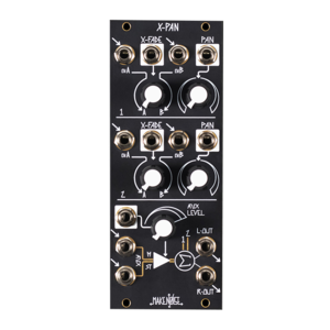
Mixer
Make Noise X-PAN 模組化合成器 XPAN
Make Noise X-PAN 模組化合成器 XPAN
NT 9,500
Price
NT
9,200
NT 9,500
Price
NT
9,200
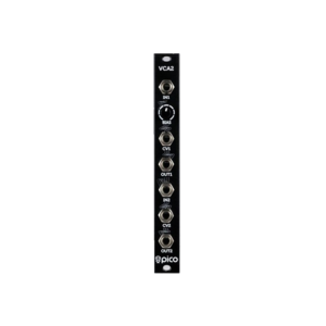
VCA
Erica Synths Pico VCA2
Erica Synths Pico VCA2
Price
NT
3,850
Price
NT
3,850
-21%
Utility
Tiptop Audio Wayout8 Patchbay 訊號分配模組
Tiptop Audio Wayout8 Patchbay 訊號分配模組
NT 1,900
Price
NT
1,500
NT 1,900
Price
NT
1,500

NEW
Utility
Expert Sleepers NTX-8CV MIDI-CV Int...
Expert Sleepers NTX-8CV MIDI-CV Int...
Price
NT
7,500
Price
NT
7,500
目前尚無評論