NT$ 14,800
首頁 » 模組化合成器 » VCO » WMD Synchrodyne Expand
Added features for more control
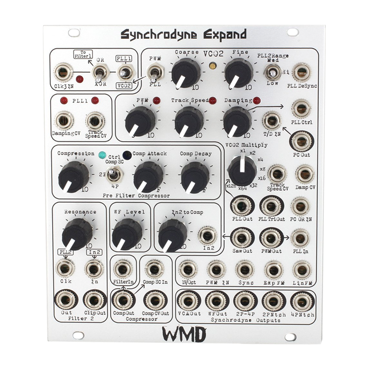
This is the WMD Synchrodyne Expand, we went a little crazy with it. But we figured that if you can grasp the original, you're the type that always wants to go deeper. So lets take this plunge together as we attempt to explain what it all means.
- Even more control than before!
- 2nd oscillator
- Another filter for more wacky sounds
- Pre filter compressor to reduce distortion inside the core
Synchrodyne Expand Concept
The Synchrodyne by itself is capable of a great deal, containing several modules in one, prepatched internally to create a vibrant range of sounds. It was difficult to cut many of the control capabilities from the Synchrodyne to keep it within the scope of an analog switched-capacitor filter module. The expand lets us bring many of the little nuances of the Synchrodyne to the patchable world.
It is designed to be powerful and extremely dynamic when minimally patched, but when patch cords start flying around to be open and experimental. You may also use many of the parts of the Synchrodyne and Expand separately in various parts of your patches. The open architecture allows it to do many jobs, even small ones.
VCO2 / PLL2
VCO2 contains an identical saw core oscillator as on the Synchrodyne. The peripherals are slightly different, emphasizing different control points. The PLL frequency multiplier is similar to that on the Synchrodyne with many additional patch points.
1V/Oct Input - Calibrated input for pitch control. The VCO will track at least 5 octaves using this input. This may be calibrated by the front mounted trim pot between the Coarse and Fine knobs.
PWM Input & Knob - CV control over the PWM (Pulse Width Modulation) of VCO2. Very powerful for controlling the Filter Core when both VCOs are combined. Control knob provides static PWM amount. It is added to CV signal when CV is applied.
Sync Input - Rising edge sawtooth reset/sync input. Does not affect slope of sawtooth.
Coarse & Fine Knobs - Coarse knob adjust the frequency of the VCO throughout its full range. Use the Fine knob to tune the oscillator within approximately 1/3 octave range.
Exp FM - This input jack provides 1/3 V/octave exponential control to the VCO core.
Lin FM - This input provides linear frequency control to the VCO core. It is DC coupled.
Saw Output - The Sawtooth output is available here. Its level is approximately +-4.5 volts.
PWM Output - Presents the output of the PWM modulated waveform.
PLL Input - This input runs into PLL2, it is normaled from the PWM output of the VCO. Use an external VCO to control the PLL by patching here.
PLL Output - Square wave raw output of the PLL frequency multiplier. This output is in a feedback loop with the VCO2 Multiply control to provide multiplication of the frequency.
PLL Triangle Output - This output is a hacked triangle wave from the PLL core. It's not a perfect triangle but is close. It's great for softer sounds in the audio range.
PC OR IN - This input is logical ORed to the phase comparator on the PLL. Applying a clock or gate signal can produce frequency variance, destabilization or total melt down. Very experimental input.
Track Speed Control & CV Input - Track speed is part of the PLL Cores self-stabilization of the phase locked loop. More track speed means that the PLL will attempt to track the frequency more accurately and stabilize faster. Tracking too fast can cause total breakdown of the loop and result in some unstable and interesting timbres. LED shows the strength of the track speed.
Damping Control & CV Input - Damping is the other half of the stabilization circuitry inside the PLL core. Higher damping means that frequency control circuit will resist change more. Use this to tame high Track Speeds. CV input allows for external control of the Damping. LED shows the strength of the Damping circuit.
PC Out - This is the Phase Comparator's direct output. It is a tri-state output (0V, 5V or high-impedance/floating). This is normaled to the Track/Damp circuitry to provide the control signal for the PLL's frequency output. This output is intended to be run through a slew limiter and back into the PLL Ctrl or T/D In. Though other uses may be found.
T/D Input - This is a direct input to the Tracking Damping circuitry. It normally expects a tri-state signal but it can handle other things. Very experimental input.
PLL Ctrl Input - This input is the direct line to the PLL frequency circuit. Plugging voltages in to this will cause direct control over the PLL and many of the prior circuits will be ignored including Track/Damp and Multiply. Very experimental and useful for further processing of the Phase Comparator signal.
PLL DeSync Input - This input is a DC couple short circuit to the PLL. A signal higher than 1V here will kill the PLL requiring it to resynchronize with itself.
PLL2 Range Switch - This switch changes the maximum range of the PLL by changing the PLL's frequency generation capacitor. Hi provides the full range. Medium and Low provide a much smaller range, limited to audio frequencies. Medium and Low also cause the PLL Triangle Output to sound different.
PWM/PLL Switch - This switch determines whether the PWM signal or the PLL signal go to the VCO2 section of the clock select switch.
Filter Clock Control
This box in the top left of the Synchrodyne Expand controls the filter clock on the Synchrodyne. There are three possible clock sources for the filter core.
Clock Control Switch - This toggle on the far right of the box selects which clock source runs the filter core. Top position lets PLL1 on the Synchrodyne control the clock. Bottom position lets PLL2/VCO2 control the clock. Middle position combines the clocks and lets them fight each other.
OR / XOR Switch - This toggle switch controls how multiple clock signals are combined. XOR mode combines the clocks in a fairly additive manner. OR mode is more aggressive and gives each clock signal more power to disrupt the other signal.
Clk3 Input - This jack provides an additional input to the Filter core. It is combined in the mode chosen by the OR / XOR switch.
LED - Shows the clock status directly. Much of the time this will be too fast to see.
PLL1 CV Inputs
This small box contains inputs for Track Speed And Damping for the PLL in the Synchrodyne.
Damping CV - This input gives CV control to Damping on PLL1. To achieve full damping (fully CW rotation of the knob on PLL1), the Damping Knob on PLL1 must be fully Clockwise. This is because the CV control and knob are in series with each other. This jack is normaled to +5 volts so that it is always at a high damping, allowing the knob OR the CV control to have an effect whether CV is used or not.
Track Speed CV - This input provides CV control over Track Speed on PLL1. This CV signal is in parallel with the Track Speed knob on the Synchrodyne. Therefore, minimum track speed is achieved with the knob fully CCW and 0V on the CV input. Maximum track speed may be achieved by the knob OR the CV input being CW or shown 5 volts respectively.
Pre Filter Compressor
The Synchrodyne's filter core can produce very dynamic material with high resonance, especially in 4 pole mode. So we added a pre filter compressor to reduce distortion inside the core. The concept here is a feedback compressor that reduces the signal level going into the core based on the level on the core's output. This is a vactrol based compressor.
The signal seen by the compressor is a mix of the VCA/Fold switch and In2.
Ctrl Switch - This switch determines where the compression circuit looks for waveform information. Comp SC looks at the Comp SC In jack. 2P looks at the selected 2 Pole output from the Synchrodyne's panel, and 4P looks at the selected 4 Pole output.
Comp SC In - This input normally sees the signal from the Compressor's output. This lets you compress the signal flowing to the filter core based on another signal. If nothing is plugged in, you have normal compression based on the level of the input signal.
Compression - This controls the overall amount of compression done to the input waveform. Fully CCW will be no compression. Fully CW will be close to limiting. Amount of compression is indicated on the blue LED.
Blue Threshold Trim Pot - This trim pot between Ctrl and Comp Attack allows you to change the threshold of compression. Turn up for compression to come on sooner. This is similar to the Compression control and was not necessary to bring out as a full control.
Comp Attack - This sets the attack speed of the Compressor. It works with the Decay speed and has bearing on the overall amount of compression.
Comp Decay - This sets the decay speed of the Compressor. If it is too high and Comp Attack is not high enough, the compressor will not compress.
Comp Out - This output produces the compressed signal for use elsewhere. It is normaled to the Filter Input.
Comp CV Out - This is the CV control envelope signal as an output.
Filter 2
Filter 2 is a second switched capacitor filter. It is a 4-Pole Low Pass type with an interesting resonance circuit. It resonates 180 degrees out of phase with the input signal. It will happily self resonate and makes a good sine wave oscillator.
Clk In - This input provides the high-speed clock to Filter 2. It is normaled from the output of PLL2.
In - This is the signal input to the filter. It is normaled from the In 2 jack and attenuator.
Out - 4-Pole Low Pass output of Filter 2.
Clip Out - Amplified diode rectified output signal from the feedback resonance stage of Filter 2.
Resonance Knob - This controls the amount of resonance. It will self oscillate and this controls the level of oscillation.
Other Inputs / Outputs / Controls
Filter In - This input runs directly to the filter core. It bypasses everything on the front end: VCA, Wavefolder, Compressor, In2.
In 2 to Comp - This jack and attenuator provide a second input to the compressor and then to the filter core. It is normaled from the Saw Output of VCO2.
WF (Wavefolder) Level - This control replaces the blue trimmer on the back of the Synchrodyne giving you direct control over the amplification of the wavefolded signal.
VCA Out - Direct out of the VCA on the Synchrodyne.
WF Out - Direct out of the Wavefolder on the Synchrodyne.
2P - 4P - Subtractive output where 4P output is subtracted from the 2P output. Produces a band-pass sort of sound. Nicer at lower resonances.
2P Notch - This is the notch output from the 2-pole filter on the Synchrodyne. It is a true notch filter where resonance controls the width of the notch. Higher resonances yield narrower notches.
4P Notch - This output is not a true notch output. The 2-pole output (HP/BP/LP) is filtered by the last 2 poles of the filter internally, and the notch from that is output here. It is more of an elliptic output than a true notch because of this.
Specs:
- Power: +12V = 90mA; -12V = 80mA
- The majority of the audio circuitry runs at +-5 volts and uses high-speed rail to rail opamps.
- Size: 22HP
- Depth: 40mm
- Every WMD product is warranted for 12 months after purchase, but please contact us if you ever have problems. We will take care of you.


使用評論:
購物須知 Q&A
Q1 . 何謂鑑賞期?
依消費者保護法之規定,網路購物享有商品到貨日起算七天猶豫期。必須提醒您,「 猶豫期並非試用期 」,鑑賞期目的為提供您檢視、參考,並非提供您商品的試用,若您收到商品經檢視後有任何不合意之處,請勿拆封使用,並立即依照退貨規定辦理退貨。商品退換貨必須是完整包裝,且勿缺漏各項配件及贈品,或自行拆損原廠包裝與外盒。若有任何遺失、損毀或是缺件,可能會影響到您的退換貨權益,也可能依照損毀狀況扣除復原之相關費用。
Q2 . 如何辦理退換貨?
若您確定要辦理退貨,請務必保持商品全新完整包裝,且勿損毀原廠外盒。包含商品本體、配件、保證書、原廠包裝、附隨說明文件等,均須包含在內,勿缺漏任何一項。若有其他可歸責您的原因,造成商品損毀,將無法辦理退貨,或須將損壞費用於退款中扣抵。但商品如有新品瑕疵問題,則不在此限,享有無條件退換貨服務。
請於鑑賞期內來電或來信,詳細告知我們欲退換貨之原因、商品現況、電話,及取件的地址,我們將於 3 - 5 個工作天內安排退貨事宜。
Q3 . 如何收到退款、需要多少時間?
依不同付款方式,退款方式與時間也不同,說明如下:
信用卡付款:待我們收到退貨商品後約 5 至 7 個工作天,款項將會退至您信用卡帳戶。請依信用卡結帳日判斷,刷退款項可能列於本月或次月帳單,退款進程請向信用卡發卡銀行確認。
匯款:請聯絡 service [at] digilog.tw 並提供您的完整匯款資料(銀行、分行名稱、銀行代號、戶名、帳號),我們將派快遞公司前去取回您的退換貨商品,並於 5 至 7 個工作天,將款項匯還至您所指定的帳戶。
Q4 . 商品維修的運費需要自行負擔嗎?
商品維修的往返運費須自行負擔。
你可能會有興趣的商品:
-4%
Envelope
4ms Pingable Envelope Generator (PE...
4ms Pingable Envelope Generator (PE...
NT 12,000
網路價
NT
11,500
NT 12,000
網路價
NT
11,500

In/Out
Expert Sleepers ESX-8CV mk2
Expert Sleepers ESX-8CV mk2
網路價
NT
6,500
網路價
NT
6,500
-7%
Sampler
4ms Stereo Triggered Sampler (STS) ...
4ms Stereo Triggered Sampler (STS) ...
NT 16,200
網路價
NT
15,000
NT 16,200
網路價
NT
15,000
Filter
Tiptop Audio Forbidden Planet Analo...
Tiptop Audio Forbidden Planet Analo...
網路價
NT
4,150
網路價
NT
4,150
-7%
VCO
Noise Engineering Ataraxic Iteritas...
Noise Engineering Ataraxic Iteritas...
NT 14,200
網路價
NT
13,200
NT 14,200
網路價
NT
13,200

VCO
Endorphin.es Furthrrrr Generator
Endorphin.es Furthrrrr Generator
網路價
NT
14,990
網路價
NT
14,990
目前尚無評論